
TLDR:

Let's start with a quick refresher on DC vs AC voltage:
- DC: constant voltage over time (\(t\)), steady-state flow
- AC: voltage oscillates over \(t\)
And review transistors quickly:
- It acts like an amplifier/switch (the equivalent of a valve for fluids)
- Think of a valve allowing fluid to flow. Want more flow? Turn the valve. Want less? Turn it the other way
- Instead of manually turning the valve, what if you could control it with a signal?
- One step further: what if instead of controlling fluid flow, this valve controlled the flow of electricity: that's a transistor
- A transistor has 3 parts
- Base (B): (control input, like the valve actuator)
- Collector (C): in our circuit current flows in from the 9V supply here
- Emitter (E): in our circuit, this is where current flows out to ground
- Two types of transistor: NPN and PNP
The Bazz Fuss Circuit
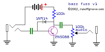
Let's start by taking a look at the circuit at rest. There's many variations of the bazz fuss, but at its core are the diode and transistor causing both amplification and clipping.
Talking amplification, we can go back to our valve analogy. A screw (or wedge wrapped around a cylinder) is a way to amplify force. Think of twisting a hand screw to open a dam valve vs. trying to vertically lift and lower the gate yourself. Instead of mechanical movement, a transistor works with currents and voltages.
Transistors and amplification
In a transistor, small changes to the CURRENT at the base causes large changes to the CURRENT at the collector. The way we control that base current is through a control VOLTAGE to the base. The base-emitter junction acts like a diode, so we can derive a relationship between the base voltage and base current from the Shockley diode equaton:
$$I_D = I_S \left(e^{\frac{V_D}{nV_T}} -1 \right)$$
There's a lot going on here, but since we just care about the base emitter diode junction and the base current (and the general nature of the relationship rather than the exact constants) we can simplify:
$$I_B \propto e^{\frac{V_{BE}}{V_T}}$$
(There's some temperature dependence, which is where the \(V_T\) comes in) but there's a general exponential relationship between the base current and the voltage. Though the voltage at the base is what we're actually controlling, I find it a little easier to think of a transistor as a current amplification device.
The gain (amplification) calculation that we follow for a transistor tracks input current. So we can surmise that a change in the voltage at the base leads to an exponential change in the current at the base, which is then amplified by the transistor's gain, as in the gain equation below.
$$I_C = \beta I_B$$
Here, \(\beta\) is the current gain (100-400x is a typical value for small-signal transistors. The 2N3904 that's used in the Quick Fuzz has a gain that ranges from 100-300x. A beefier transistor like an MPSA13 Darlington can have a gain ranging up to ~10,000+ times).

For an NPN transistor (like the 2N3904 in the clean fuzz, a 2N5088 or an MPSA13)
- a small current flows into the base
- this controls a larger current flowing in from the collector
- both of these currents flow out through the emitter
For a PNP, the current's flipped:
- current flows OUT of the base
- this controls a larger current flowing OUT of the collector
- with the source of both of these currents coming in from the emitter
Bias Voltage and the Transistor's Operating Point
Let's take a look at the MAS effects Quick Fuzz. We haven't plugged our guitar into the input jack yet, but it's powered with the +9V positive supply voltage (VCC)

Current from the 9V flows through the resistor and the diode. Diodes have their own forward voltage drop (e.g. 0.7V for Si diodes, 1.2-2.1V for different colored LEDs, 0.2-0.5V for Ge diodes.). This takes the base voltage below the collector voltage.
$$V_B = V_C - 0.7\text{[V]}$$
You have some current going through the diode providing a steady DC voltage to the base. This causes a steady DC current to flow from base to emitter, which controls a larger steady DC current flowing from collector to emitter to ground. The transistor's in its operating window, ready to amplify.
This is where the magic of the bazz fuss comes into play, what we've set up is a really unstable bias: D1 tries to maintain a steady state relationship (VB = VC-0.7), but the guitar signal will soon mess this up. It's like a proportional controller (with insufficient gain) trying to regulate rapidly fluctuating disturbances. It simply can't keep up, and the system fluctuates around the setpoint instead of holding steady.
Your guitar's basically a large sensor that works via electromagnetic induction. The pickup contains a permanent magnet wrapped with a coil of wire. When the metal string vibrates, it disturbs the magnetic field, which induces an AC voltage in the coil. This small voltage signal (typically less than 1V) is the output of your guitar.

All that sounds are, are different waveforms. The sin wave produces the pure C5 tone, and the flute follows pretty closely. The guitar's signal is a lot messier: it's jam packed with harmonic overtones, attack transients (e.g. plucking/strumming), noise from the string vibration all culminating in a less clean waveform that gives a guitar its distinct timbre.
The pedal's on, and the transistor's ready to amplify. Let's plug a guitar in:
In the MAS effects pedal first the signal is met with a pull-down resistor (R2), it prevents popping when we turn the pedal on. We then pass the signal through the coupling capacitor C1: it blocks DC and allows AC to pass (also filters which frequencies can pass). C2 at the output is also a coupling capacitor but on the output: it blocks the DC voltage sitting at the collector so your AC guitar signal can pass but any DC from the +9V gets blocked.
Now the guitar's AC signal is superimposed onto the DC bias through the diode at the base. This causes the base voltage, and thus the base-emitter current, to fluctuate up and down around the bias point. These base-emitter current fluctuations cause the collector-emitter current to fluctuate by $\beta$ times as much (remember: this is our amplification gain). This collector current fluctuation creates voltage fluctuations across R1 which appears at the collector. C2 then passes these AC fluctuations to the output while blocking the DC voltage from the +9V source sitting at the collector.
That's normal transistor amplification working: but the bazz fuss mixes this up by making the amplification and clipping asymmetric by using D1 in its unstable biasing arrangement.
When you play your guitar, the signal swells (+) and (-). When the signal swings (-), the base voltage tries to drop below its bias point. The diode is like a responsive one-way valve: it sees this and says "I'll conduct more current" to pull the base back up to \(V_B = V_C-0.7\) (like reacting to low pressure, and increasing flow to bring pressure back up). But it's limited to how much current it can draw in through R1. If the 9V battery is like a reservoir/tank at fixed head pressure, the resistor is an orifice plate. It's a flow constriction limiting the maximum current available to D1 and how quickly it can respond to changes.
The current that DOES pass through upsets the collector bias, and this creates distortion. This clipping is caused by the diode in the feedback path (different from traditional diode clipping where the diodes run to ground). D1 in the Bazz Fuss serves a double role: it both biases the transistor AND clips the negative swing (by limiting how much current can flow through it - controlled by R1). The positive swing clips differently, which leads to the pedal's asymmetric distortion and rich sound.
When your guitar swings (+), the base voltage tries to go *above* its bias point. D1 doesn't conduct backwards (it's like a one-way valve) so it can't pull the base back down. This means that transistor Q1 gets a HUGE base emitter voltage increase with no limiting mechanism. Amplification gets kicked into high gear, and current through the collector increases dramatically. This is extremely strong amplification, so great that it can get to the point of saturating the transistor (the valve's 100% open, it can't increase flow any further) and the collector voltage crashes towards 0V. This hard-clips the positive peaks and leads to a much harsher distortion.
Fancy Lime on the diystompboxes forum summarized it most succinctly: One half clips via the diode, the other has the natural transistor clipping. On top of that, the biasing is different for both halves of the signal.
This asymmetric clipping generates lots of harmonics both even (2nd, 4th, 6th, ...) and odd (3rd, 5th, 7th...). Even harmonics come from the asymmetry in the processing of the positive and negative halves while the odd come from the nonlinear parts of the circuit (exponential transistor curve, clipping, etc.)
The constantly shifting bias point (operating envelope) also creates intermodulation distortion: the different frequencies in the signal mix and interact to create new sum and difference frequencies. What you end up with is a complex harmonic mess that gives a rich distorted fuzz sound.
Adjusting the Sound with Potentiometers
The QuickFuzz circuit has two potentiometers that let us adjust the effect's sound: a 100kA volume pot, and a 1kB gain pot.
Volume (100k\(\Omega\)A Audio Taper)
This one's a bit simpler than the way the gain potentiometer at the emitter is. After the output coupling capacitor C2, we connect this potentiometer at the output to act as a variable logarithmic voltage divider.

- Top lug connected to the signal from C2
- Bottom lug to ground
- Wiper (middle) to the output jack

It acts like a blend valve: when turned all the way down, the wiper connects closer to the bottom lug, routing the signal to ground. When the wiper is all the way up, the signal goes almost entirely to the output. Positions in between pass a fraction to output, and dumps the rest of the signal to ground.
The A stands for audio taper (meaning logarithmic). Human hearing is logarithmic, not linear (check out the Weber-Fechner law for more details on this). If our ears were linear, a sound that seems "twice as loud" would have 2× the power. In reality, for a sound to be perceived as twice as loud, it needs about 10× the power. This is why we measure sound in decibels (dB) - a logarithmic scale.
Because of this logarithmic perception, a linear taper pot used for volume control feels awkward:
- The first 20% of rotation creates most of the perceived volume change
- The remaining 80% seems barely responsive
- Volume feels very sensitive at low levels and "dead" at high levels

The audio taper potentiometer has a logarithmic resistance curve that matches our ear's logarithmic response to sound intensity, giving us a smooth, natural-feeling volume control where each turn of the knob produces a consistent perceived change in loudness.
Gain (1k\(\Omega\)B Linear Taper )
This potentiometer we've wired in to act as a variable resistor (in the rheostat configuration). By adding a resistor between the emitter and ground, we create local negative feedback that affects both the gain and bias stability.

As the transistor conducts more current through the collector-emitter path, the current flows through the emitter resistor to ground. Turning the potentiometer clockwise, increase the resistance from 0\(\Omega\) to 1000\(\Omega\) linearly. This creates a voltage drop across the resistor (Ohm's law: \(V=IR\)). This voltage drop raises the voltage at the emitter.
- Top lug: connected to the emitter orf the transistor
- Bottom lug: connected to the wiper (middle lug)
- Shorted bottom lug and wiper: both go to ground
By shorting one of the outer lugs to the wiper, we're using the potentiometer as a two-terminal variable resistor (rather than a three terminal voltage divider). Additionally, by shorting the unused outer lug to the wiper we prevent crackling or signal dropout by maintain continuity if the wiper ever loses contact with the resistive track.
Since the base-emitter junction is a diode junction it needs a bias voltage to be able to conduct. If we raise the emitter voltage, the effective base-emitter voltage (\(V_{BE}\)) decreases. This reduces the base current, reducing the collector current (which is what raised the emitter voltage to begin with). This configuration is a negative feedback loop that stabilizes the transistor's operating point.
This control sets how hard the transistor clips, and how the asymmetric distortion behaves. This one we want to keep linear: the relationship this pot manages is that between emitter resistance and perceived distortion, and that relationship isn't as extreme as that between output voltage and perceived loudness. Since the gain control affects both gain and bias stability (which affects clipping characteristics), the combined effect creates a somewhat non-linear response anyway. The linear pot helps keep some predictability in how the control feels as you sweep through the range.